Has it been four years since the surprise release of the Raspberry Pi Compute Module 4? Released in the heart of the pandemic, a time when shortages were rife, the Compute Module 4 brought a new form factor and features to the Raspberry Pi Compute Module range.
Fast forward to 2024, and as the year nears the end, the rumors are true, there is a new Compute Module taking the flagship spot, the Compute Module 5.
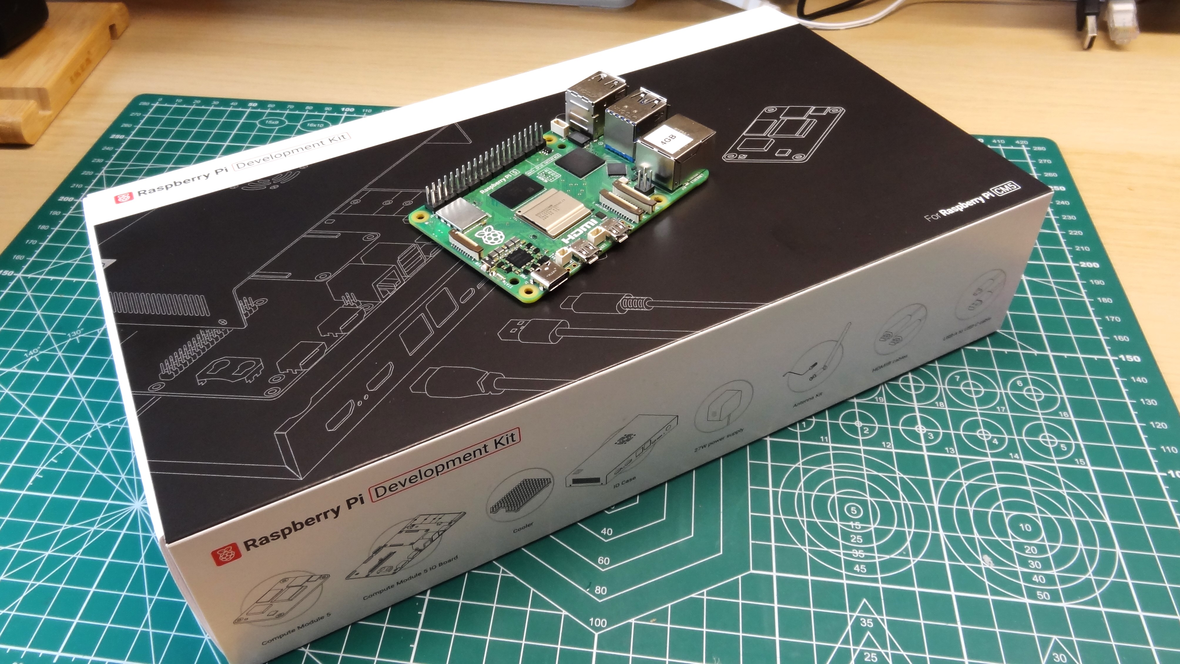
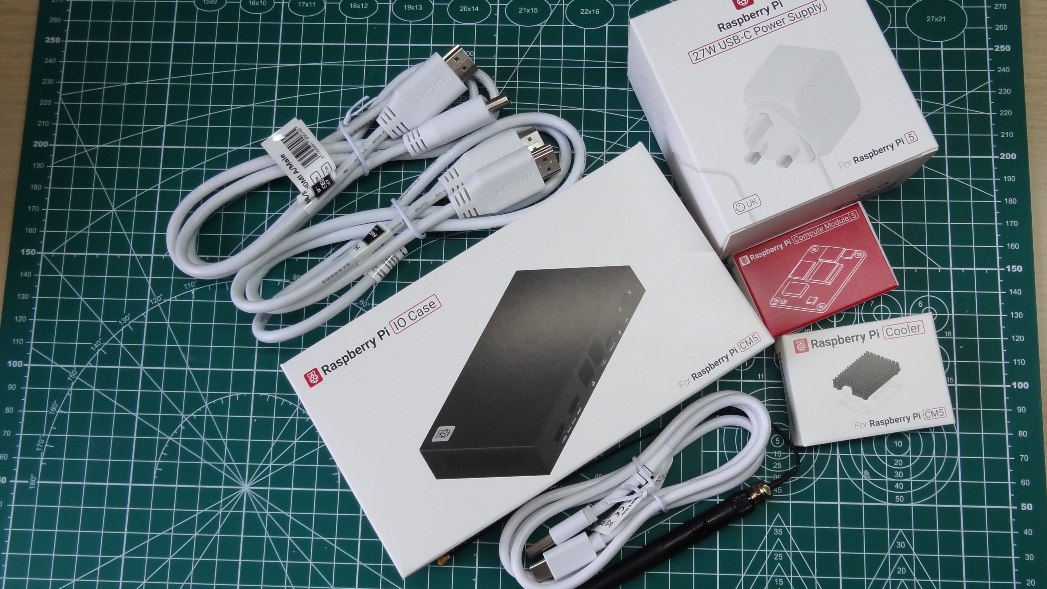
The Raspberry Pi CM5 is available in a variety of SKU. These go from $45 (£42.70) for the 2GB model with no Wi-Fi or onboard eMMC storage, to the $95 (£90) 8GB model with 64GB of eMMC and Wi-Fi. Our review unit is a $130 Raspberry Pi Compute Module 5 Development Kit which comes with
- Raspberry Pi Compute Module 5 (4GB RAM, 32GB eMMC, Wi-Fi)
- Raspberry Pi CM5 IO Board
- Raspberry Pi IO Case for CM5
- Raspberry Pi Cooler for CM5
- Raspberry Pi Antenna Kit
- Raspberry Pi 27W USB Type-C PD PSU
- 2 x Raspberry Pi HDMI Cables
- Raspberry Pi USB-A to USB-C Cable
This kit packs all of the things that we need to start developing projects and products powered by the Raspberry Pi Compute Module 5.
Is the Raspberry Pi Compute Module 5 the right choice for your next project? Should you stick with the Compute Module 4? Let’s find out!
Raspberry Pi Compute Module 5 Specifications
| Row 0 – Cell 0 | Raspberry Pi Compute Module 5 |
| SoC | BCM2712 SoC Arm Cortex-A76 64-bit quad-core CPU running at 2.4 GHz |
| Row 2 – Cell 0 | 800 MHz VideoCore VII GPU, supporting OpenGL ES 3.1, Vulkan 1.2 |
| Display | 2 x 4Kp60 HDMI display output with HDR support via IO board |
| RAM | 2,4,8GB LPDDR4X-4267 SDRAM |
| Storage | 0GB (Lite) or 16,32 or 64GB of eMMC Micro SD (SDR104 compatible) M.2 NVMe SSD via M.2 HAT |
| GPIO | 40 Pin Raspberry Pi HAT Compatible via IO board |
| USB | 1 x USB 2 2 x USB 3 (simultaneous 5Gbps) |
| Connectors | All via IO board 2 × 4-lane MIPI camera/display transceivers M.2 PCIe Gen 2.0 x1 interface |
| Networking | Via IO board |
| Wi-Fi / Bluetooth | 2.4 GHz / 5.0 GHz IEEE 802.11 b/g/n/ac wireless, Bluetooth 5 / BLE |
| Power Button | Via IO board |
| Power | 5V 5A via USB C 5V via GPIO |
| Dimensions | 55 mm × 40 mm × 4.7 mm |
Design of the Raspberry Pi Compute Module 5 & Compute Module 4 Compatibility
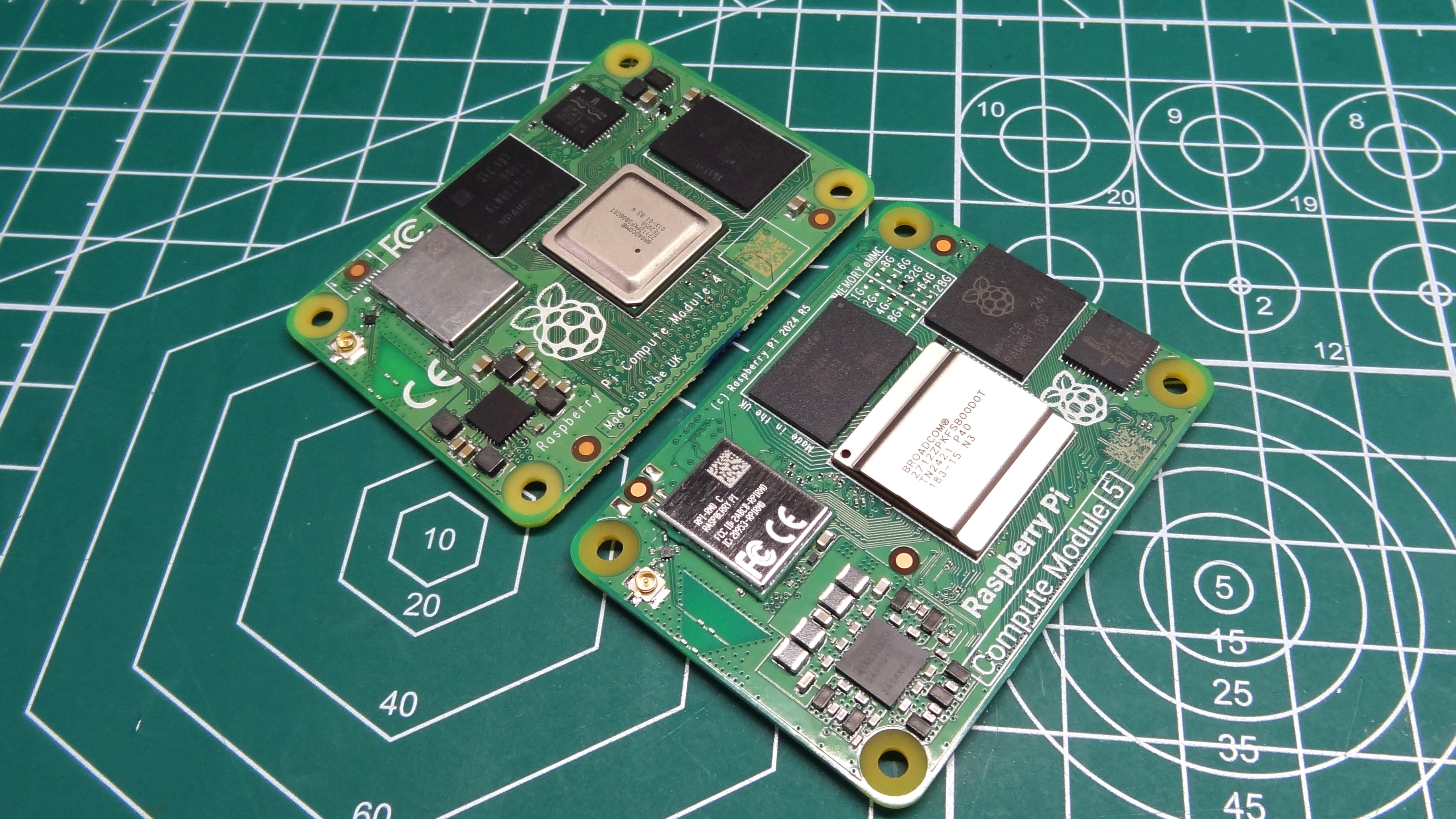
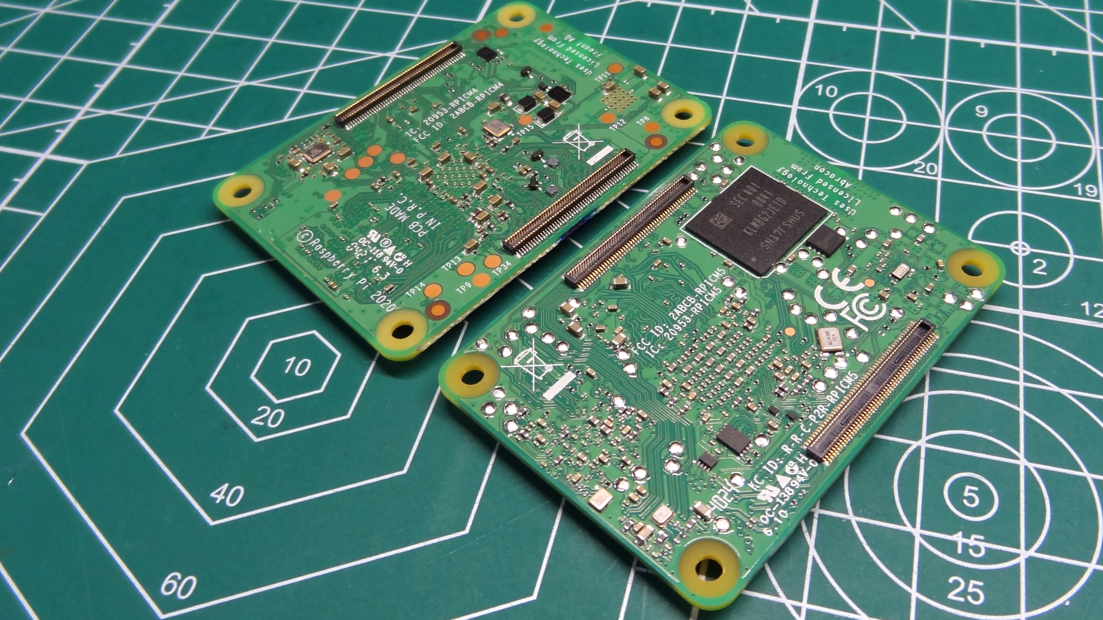
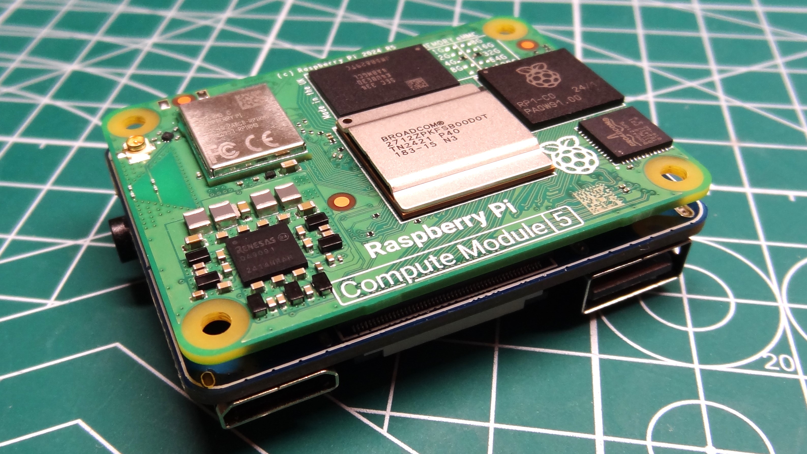
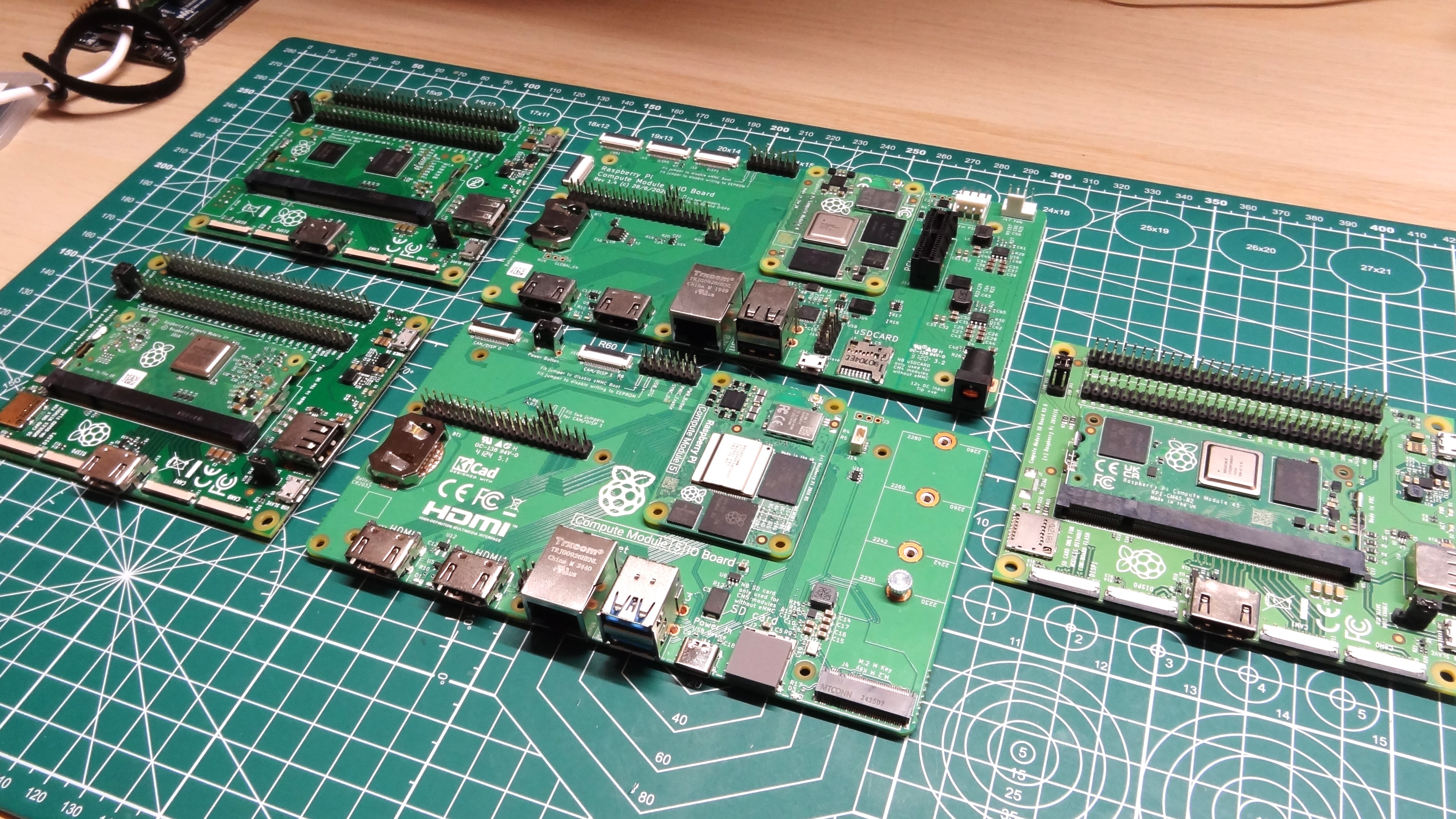
The keen eyed amongst you will have already spotted that the Compute Module 5 and 4 share the same form factor and connector. Previous models of Compute Module used a DDR2-SODIMM form factor, but the Compute Module 4 introduced a new custom connector which improved the connections between the Compute Module and the breakout board.
The Compute Module is essentially a Raspberry Pi with none of the ports physically broken out on the board. Instead the port connections are routed through the connector, for use with the IO board and your own product, via a PCB. If you don’t need Ethernet, then why have the connection? Likewise for any other port. You only breakout what you need for the product, and this saw the Compute Module being used in televisions, cameras, home entertainment systems and even electric vehicle charging stations.
The Compute Module 5 comes in eMMC and non-eMMC SKUs, and there are models with or without Wi-Fi / Bluetooth. You may be thinking, why? Industrial applications may not need or want wireless communications in a product, as it may interfere with machinery (unlikely as electronics are typically emissions tested). They also may want to use removable storage, like micro SD cards to run the OS. As we later find out, the Compute Module 5 with eMMC is just like the Compute Module 4 with eMMC, you can’t use micro SD cards.
With the same form factor and connector, can we use the Compute Module 5 with accessories designed for the Compute Module 4?
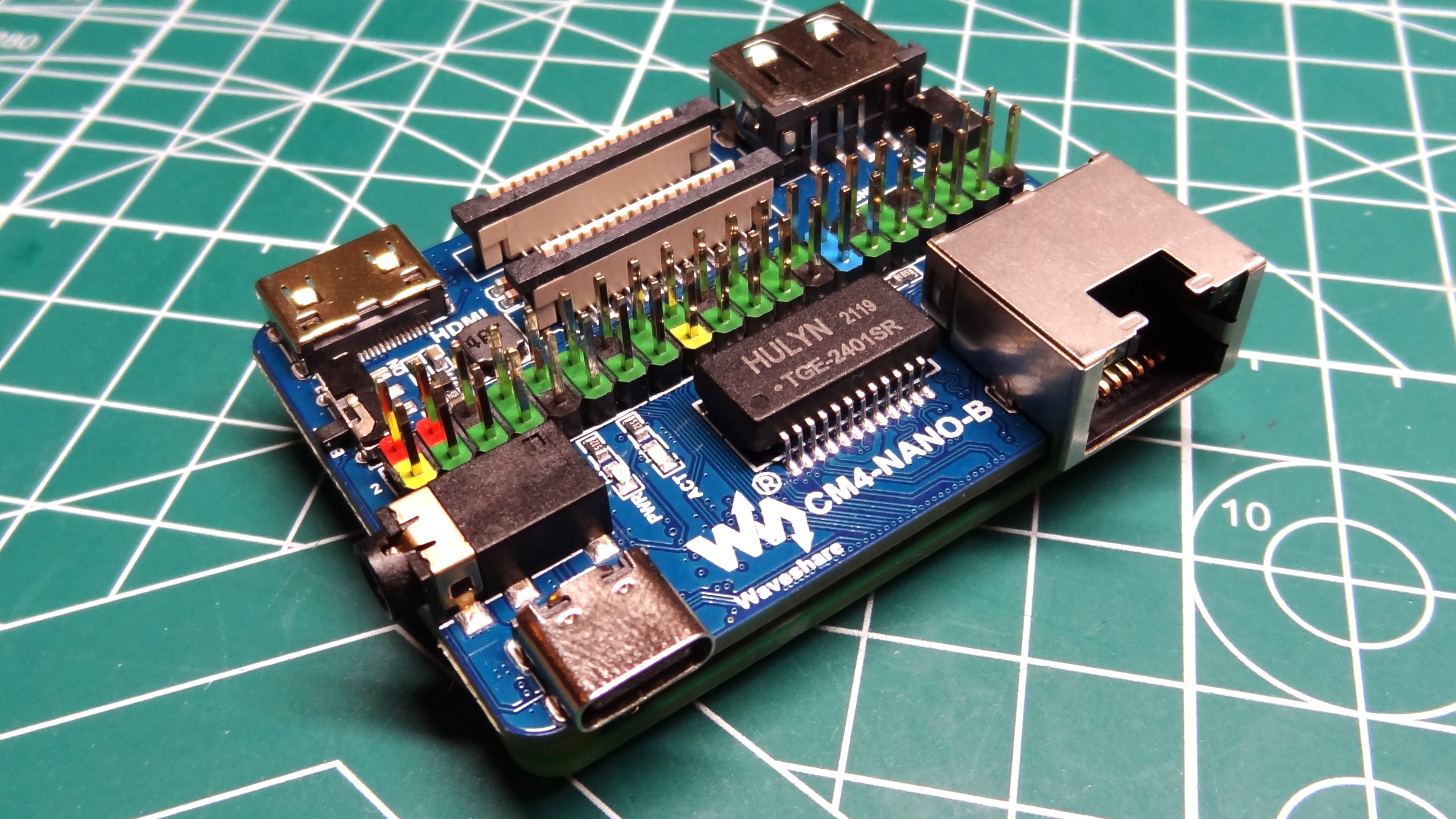
Yes, we can! I dug into my bits box and pulled out a Waveshare CM4-NANO-B board. This is an IO board shrunk down to the same size as the Compute Module 5/ We have USB C power, Mini HDMI, USB, Ethernet, connections for camera / display and a full Pi GPIO. It works!
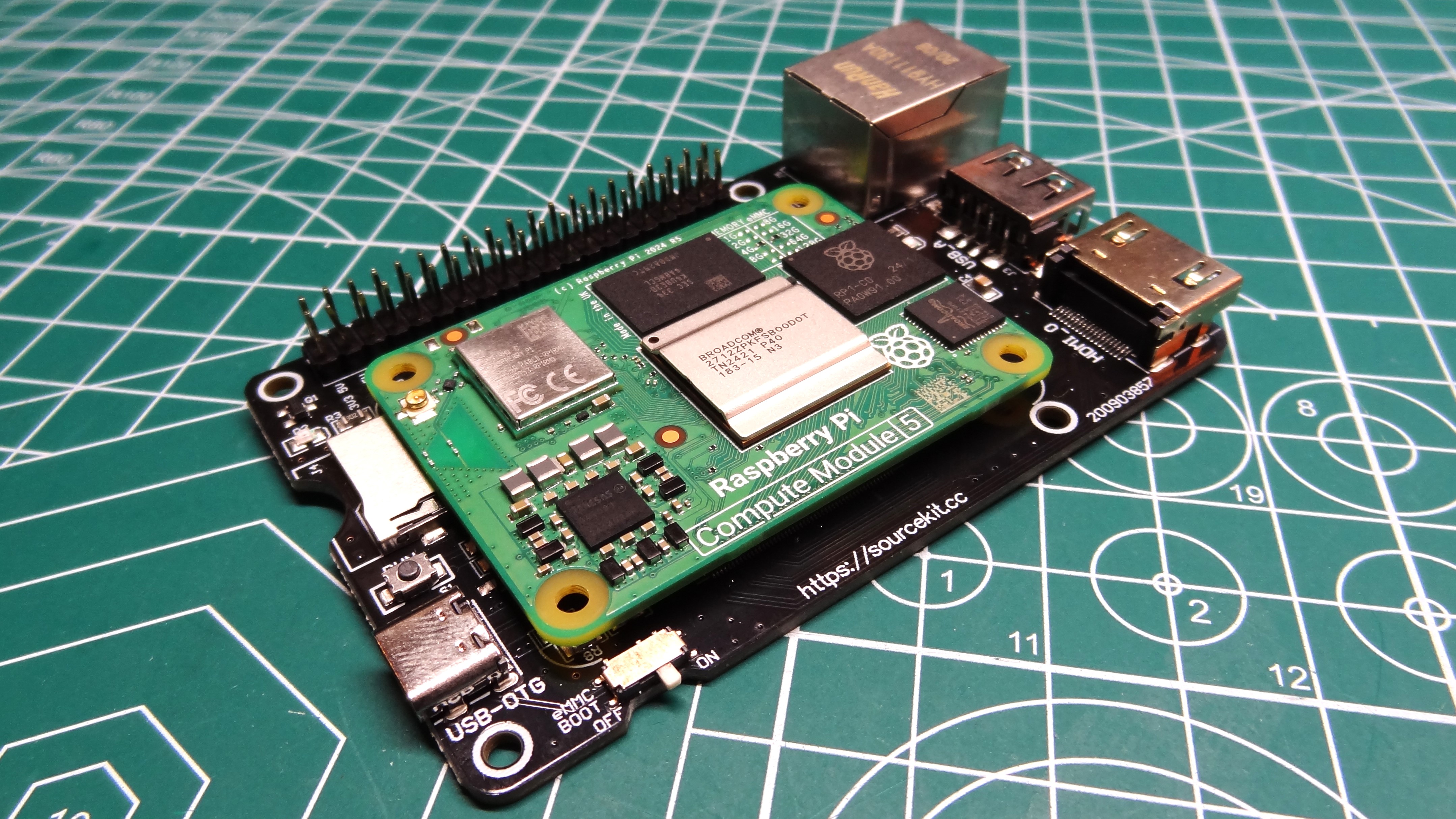
Another small Compute Module breakout board is the Sourcekit PiTray Mini, which I am sad to say does not work with the CM5. The board was completely dead, no activity or current draw.
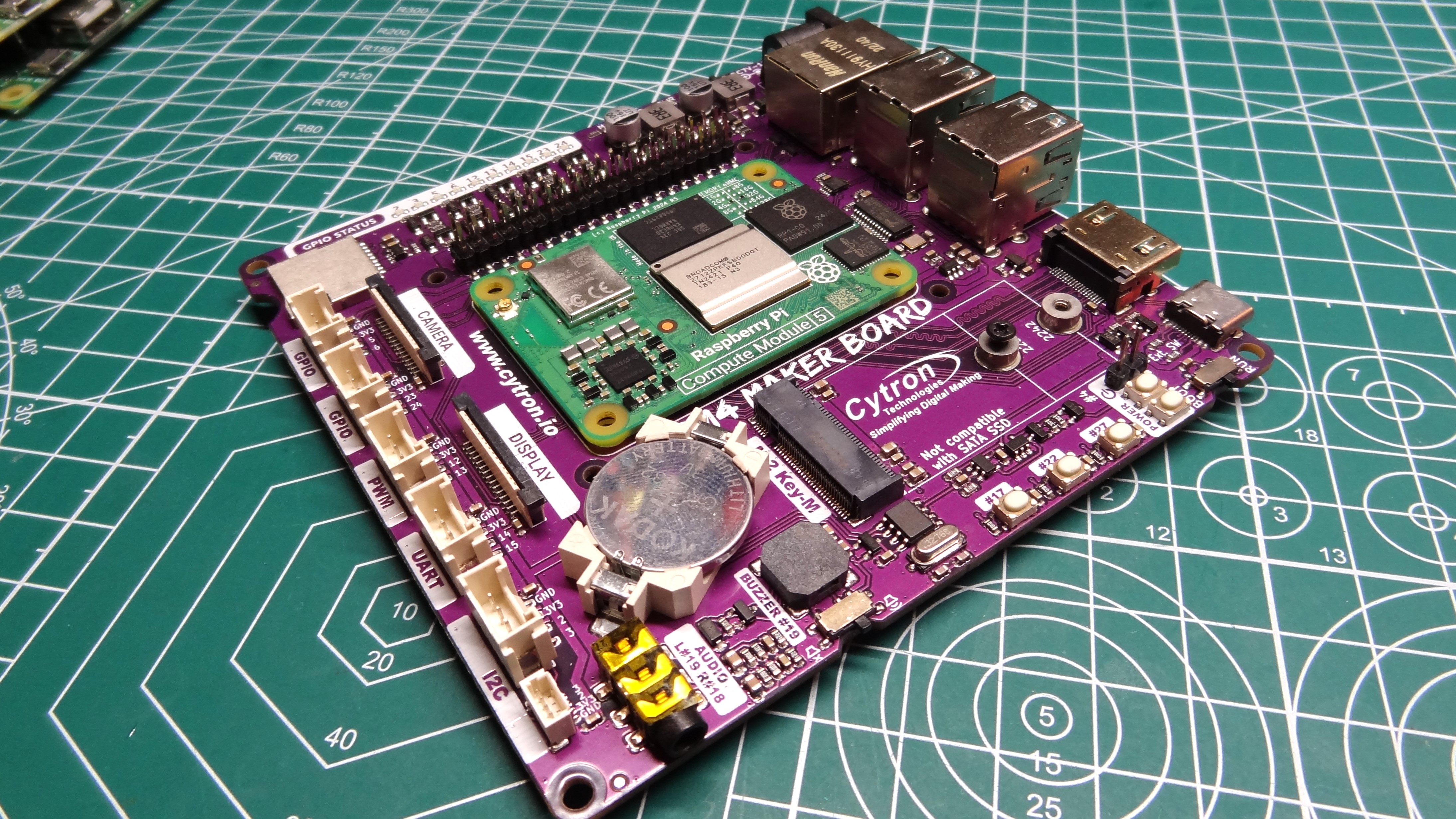
I dug a little deeper into the strata that is my bits box and pulled out the Cytron CM4 Maker Board. This also worked with the Compute Module 5, apart from only one USB port was working. The other three were non-functional. We’re sure that Cytron will release an update to address this. But the CM4 Maker Base did work with our 256GB NVMe SSD, meaning that it could become a rather useful development IO board.
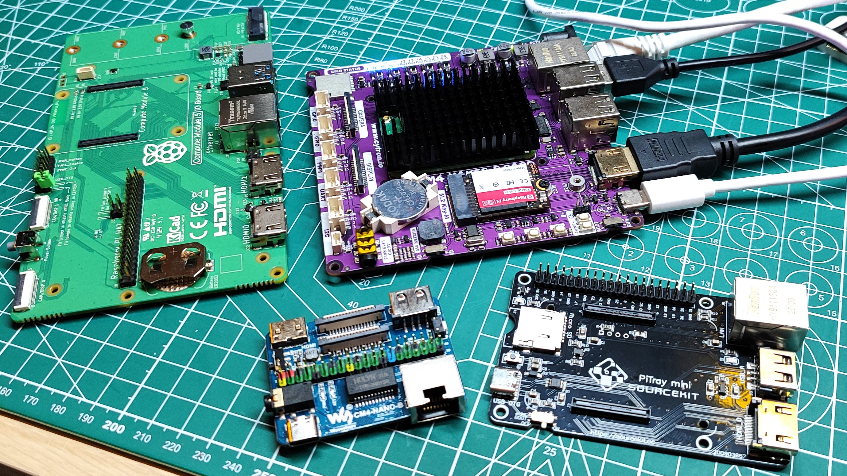
The Compute Module 5 seems to be largely compatible with older Compute Module 4 add-ons, but unless they are advertised as working with the CM5, we wouldn’t rush out to buy any of these older add-ons just yet.
Raspberry Pi Compute Module 5 Varients
Just like the Compute Module 4, the CM5 comes in a variety of RAM, storage and wireless options ranging from a $45 2GB model with no eMMC or Wi-Fi, all the way up to a $95 model with 8GB of RAM, 64GB of eMMC and wireless. We’ve compiled a table from the official Raspberry Pi Compute Module 5 product brief which details all of the available variants.
Raspberry Pi Compute Module 5 without Wi-Fi
| RAM | eMMC | MSRP (excluding sales tax) |
|---|---|---|
| 2GB | 0GB (Lite) | $45 |
| Row 1 – Cell 0 | 16GB | $50 |
| Row 2 – Cell 0 | 32GB | $55 |
| Row 3 – Cell 0 | 64GB | $60 |
| 4GB | 0GB (Lite) | $55 |
| Row 5 – Cell 0 | 16GB | $60 |
| Row 6 – Cell 0 | 32GB | $65 |
| Row 7 – Cell 0 | 64GB | $70 |
| 8GB | 0GB (Lite) | $75 |
| Row 9 – Cell 0 | 16GB | $80 |
| Row 10 – Cell 0 | 32GB | $85 |
| Row 11 – Cell 0 | 64GB | $90 |
Raspberry Pi Compute Module 5 with Wi-Fi
Can we Overclock the Raspberry Pi Compute Module 5?
Yes, we can overclock the Compute Module 5! Remember, this is essentially a Raspberry Pi 5 in a smaller form factor. To be exact, the Compute Module 5 uses the same D0 stepping as found in the Raspberry Pi 5 2GB. Much of the “dark silicon”, unused parts of the BCM2712 has been removed. This cost optimized version, according to Jeff Geerling, leads to a 33% reduction in die space. The D0 no longer has on-chip Ethernet MAC, the RP1 “Southbridge” handles that. It also means that the D0 consumes less power, but does it impact overclocking?
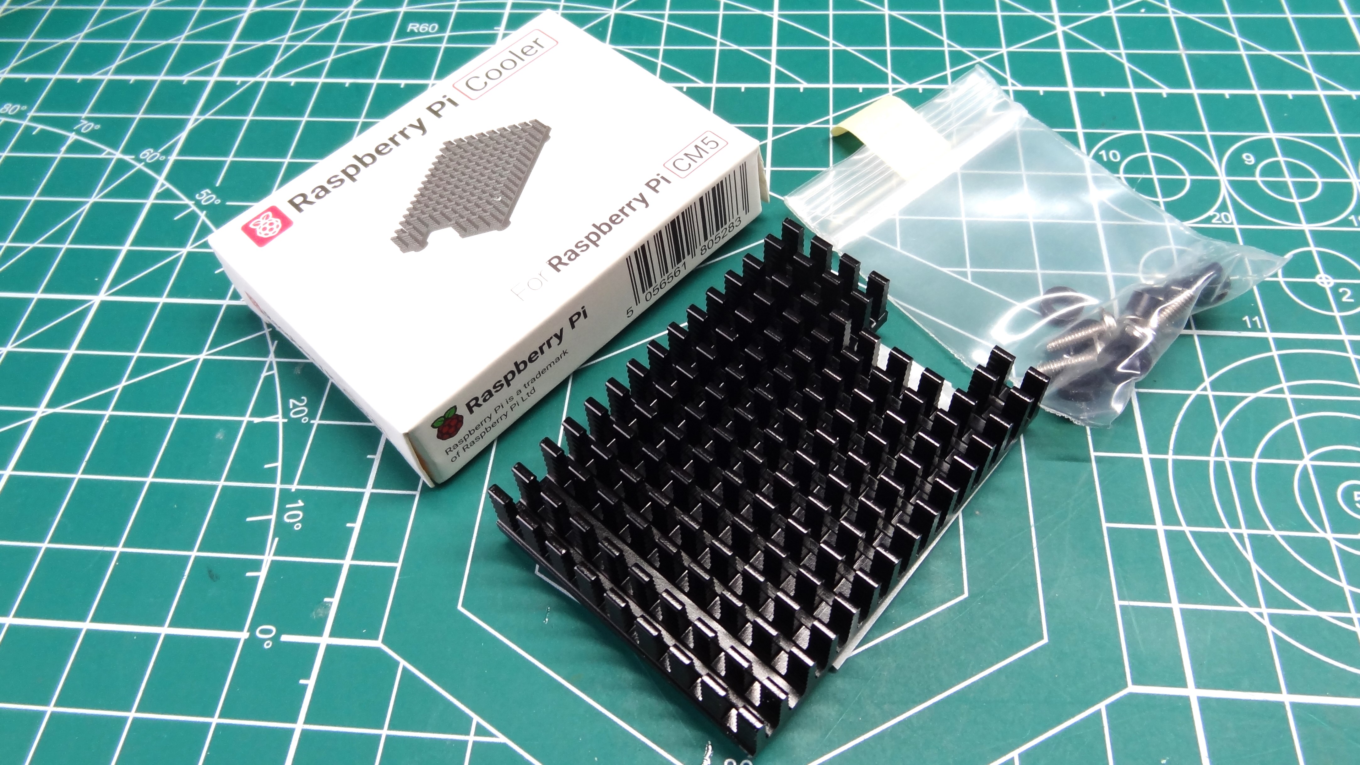
Not really, but overclocking is usually a mix of luck and persistence. I managed to overclock the Raspberry Pi compute Module 5 to 3 GHz, but I did need to give it a little more voltage, not for the faint hearted. At 3-GHz CPU and 1-GHz GPU, the Raspberry Pi Compute Module 5 was stable, but it produced a lot of heat and the included (for review) $5 passive cooler worked better than the fan cooling. Why? Because with the fan cooling, there is no heatsink to pull the heat from the System on Chip (SoC). Sure it has an IHS, but that isn’t enough to cool the SoC. Can we use the fan and heatsink at the same time? No. The fan is 2mm too thick. The best option would be to use a shorter heatsink than the supplied.
Raspberry Pi Compute Module 5 Thermal and Power Performance
I tested the Raspberry Pi Compute Module 5 in two cooling configurations. With the passive heatsink cooler attached, and with active fan cooling. The two cannot be used together due to the fan touching the heatsink. I tried removing the fan screws to release 2mm of clearance, but the fan housing still touched the heatsink.
For each cooling configuration I tested the Compute Module 5 at the stock 2.4 GHz and overclocked to 3 GHz. So let’s dig into the details.
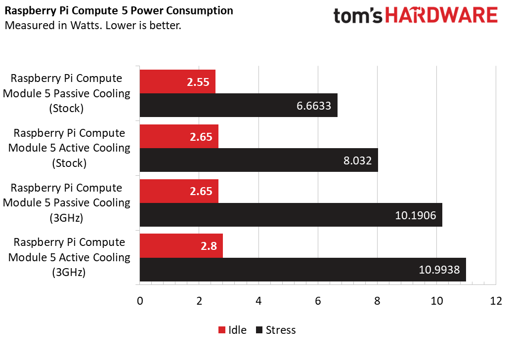
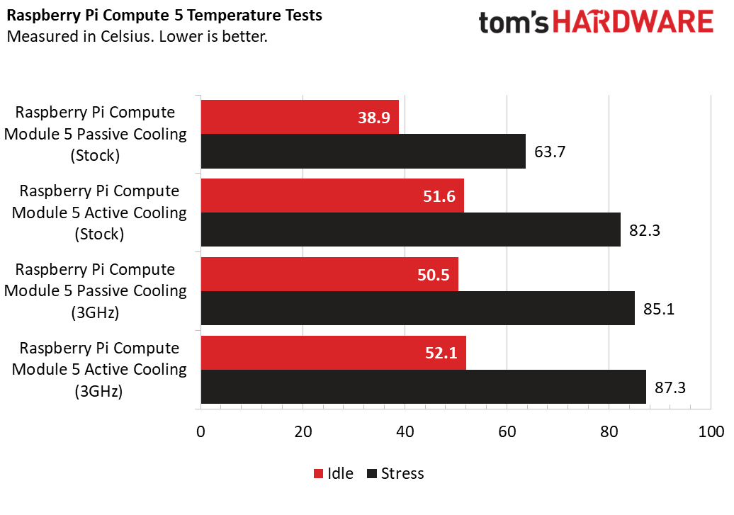
Passively cooled, the stock speed Raspberry Pi Compute Module 5 idles at 38.9 degrees Celsius, consuming 2.65 Watts of power. Putting the system under stress for five minutes, the temperature rises to 63.7°C and power usage jumps to 6.66W. The CPU temperature remains well below the 80°C throttle point.
Overclocking the CPU to 3GHz, the idle temperature sits at 50.5°C and still consumes 2.65W of power. Under stress, the CPU temp jumps to 85.1°C, and yes, it throttled! In an attempt to keep cool, the CPU will dial back the speed in an attempt to lower the CPU temp below the throttle point.
Active cooling, with the fan around 10mm away from the IHS of the SoC, the stock speed Compute Module 5 idles at 51.6°C and consumed 2.65W (again!) of power. Under a stress test, the SoC hit 82.3°C, again triggering the thermal throttle. Power consumption was 8W.
Overclocking the CPU to 3GHz, the CPU idled at 52.1°C while consuming 2.8W of power. The stress test saw the CPU temp jump to 87.3°C (the highest temperature in our tests), and consumes 10.99W.
At stock speeds, the Compute Module 5 will run happily with passive cooling, but if you are designing a product around it, take into account that it does need cooling! I’m a little disappointed with the active fan cooling. The fan is quiet, triggering when the CPU goes above 60°C, but the distance from the IHS, and the issue of heatsink compatibility means that the SoC will get far too hot, too quickly. We really need a low profile heatsink and active cooling to get the best cooling performance.
Raspberry Pi Compute Module 5 eMMC and NVMe SSD Performance
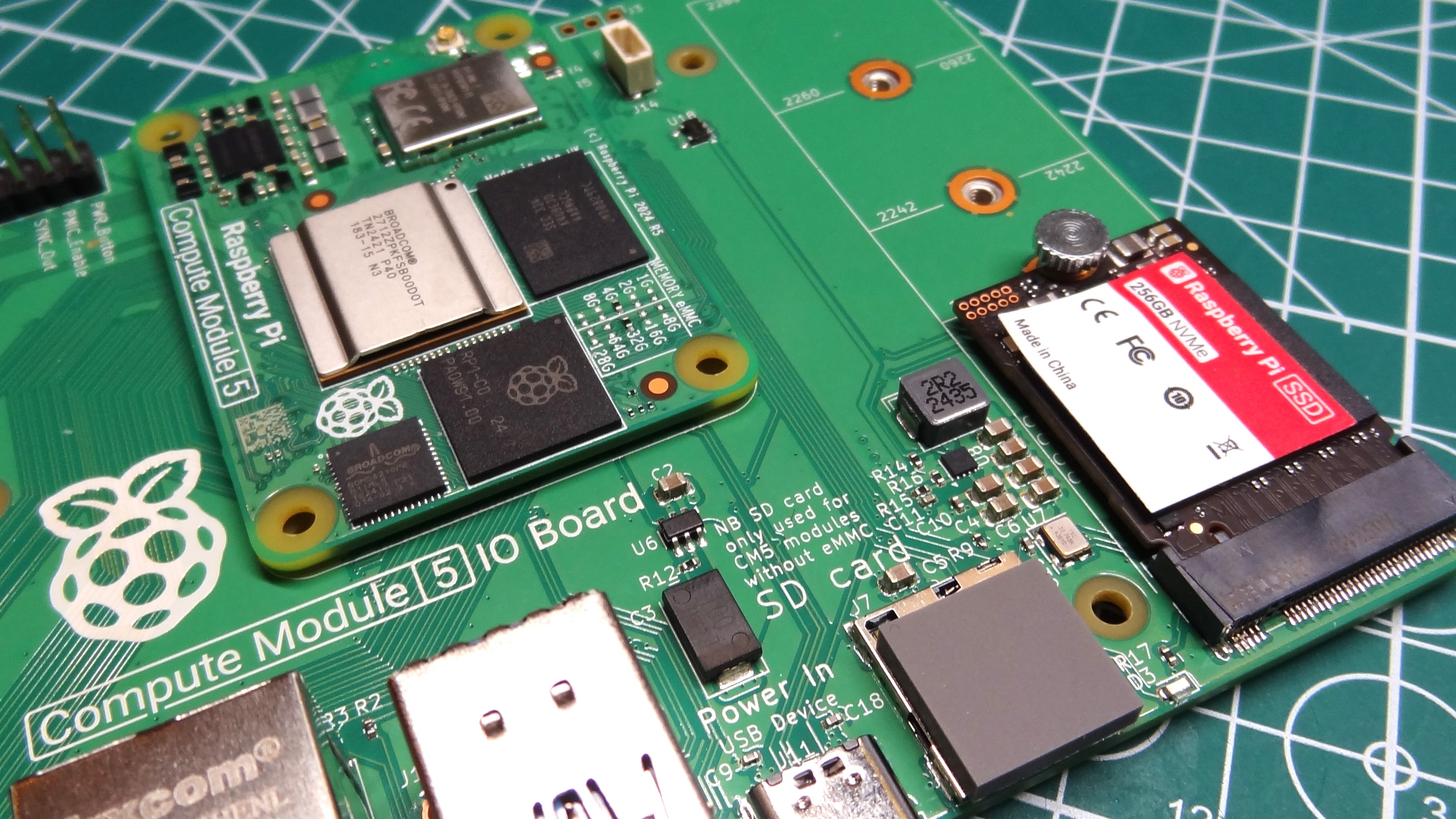
To cut a long story short, the eMMC performance on the Compute Module 5 is akin to PCIe Gen 2 NVMe SSD speeds. This is much faster than even the best micro SD cards can muster, but still only half what PCIe Gen 3 provides. I tested eMMC and NVMe SSD boot times, and bandwidth. Then I compared the results with the Raspberry Pi 5 4GB (I explain why during the test).
| Header Cell – Column 0 | Boot Time (Seconds) | Read Speed (MB/s) | Write Speed (MB/s) |
|---|---|---|---|
| Raspberry Pi Compute Module 5 eMMC | 17.59 | 343 | 106.3 |
| Raspberry Pi Compute Module 5 NVMe (Gen 3) | 17.39 | 768 | 703 |
| Raspberry Pi 5 4 GB A2 Micro SD | 20.84 | 93.5 | 30.8 |
Boot times were fast! The benchmark was a Raspberry Pi 5 32GB A4 micro SD card, running the latest Raspberry Pi OS. Why a Pi 5? The Raspberry Pi Compute Module 5 with eMMC, just like the 4 before it, cannot boot from micro SD (it even says so on the CM5IO silkscreen print, just above the micro SD card slot).
Models without eMMC can boot from micro SD, but we did not have one for testing. I confirmed that the Compute Module 5 with eMMC cannot boot from micro SD with Raspberry Pi CTO Gordon Hollingworth. The Pi 5 was the next best option. Ok, with that out of the way lets talk boot times.
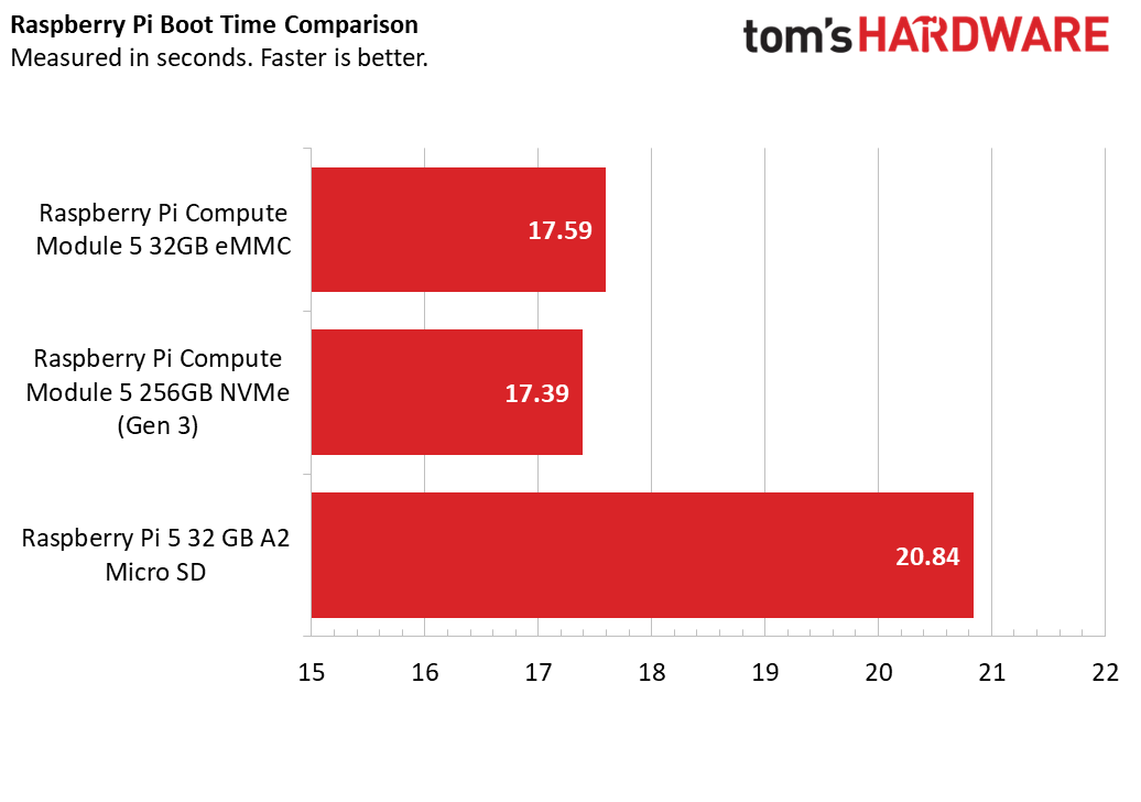
Micro SD boot time was 20.84 seconds, respectable, and shows that the new A2 micro SD cards are a good alternative. The eMMC and NVMe boot times were spookily very similar. The eMMC managed 17.59 seconds, NVMe (Gen 3) 17.39 seconds.
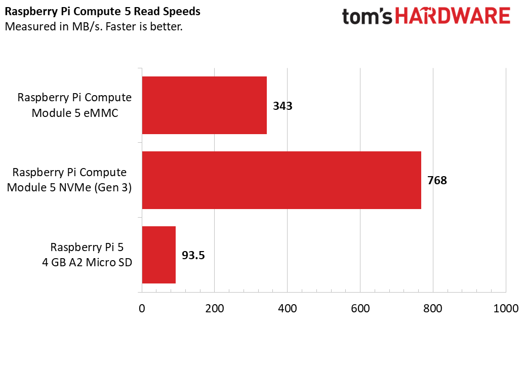
Using dd, I read the contents of the 32GB eMMC to /dev/null to see how fast the drive would read. I managed a respectable 343 MB/s. I did the the same with the Raspberry Pi branded 256GB NVMe SSD running at PCIe Gen 3, which hit 768 MB/s. If you crave the ultimate performance, then NVMe SSD is the way to go. But, if you intend to build the Compute Module 5 into a product, then the eMMC read speed is plenty fast.
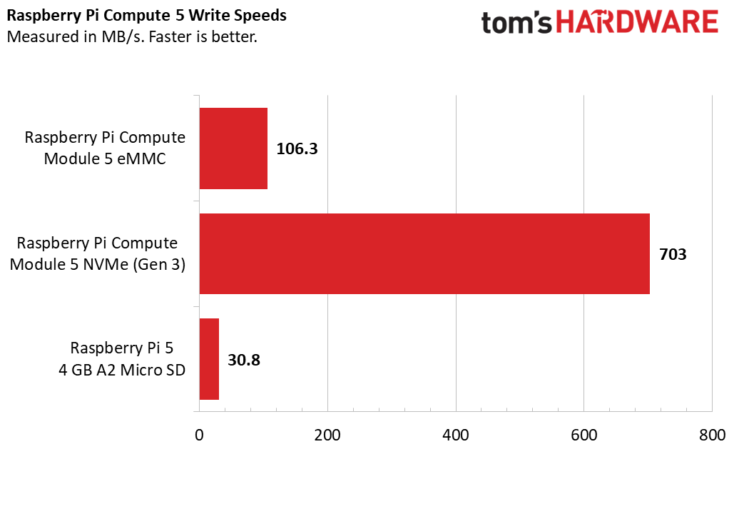
So what about eMMC and NVMe write speeds? For this I used the Raspberry Pi Diagnostics tool and took the sequential write speed as the benchmark. The eMMC write speed was 106.3MB/s, not bad but the PCIe Gen 3 NVMe SSD’s 703 MB/s blows it out of the water.
How do these speeds compare to Raspberry Pi branded A2 micro SD cards? The read speed for our Pi-branded 32GB A2 micro SD was 93.5 MB/s, and the sequential write speed was just 30.8 MB/s. Pretty good considering the cost and ease of use, but only useful if your Compute Module 5 has no eMMC.
After all this testing, It seems that eMMC offers the best balance of performance and form factor. With eMMC we can have a speedy storage device, embedded into the Compute Module 5’s form factor. This would be the best option for those of us designing products based on the Compute Module 5. Should we need faster storage, then Raspberry Pi’s recent foray into PCIe based storage is now bearing fruit, and we potentially have a powerful Arm desktop computer, now with a new form factor.
The Raspberry Pi 5 Compute Module 5 IO Board
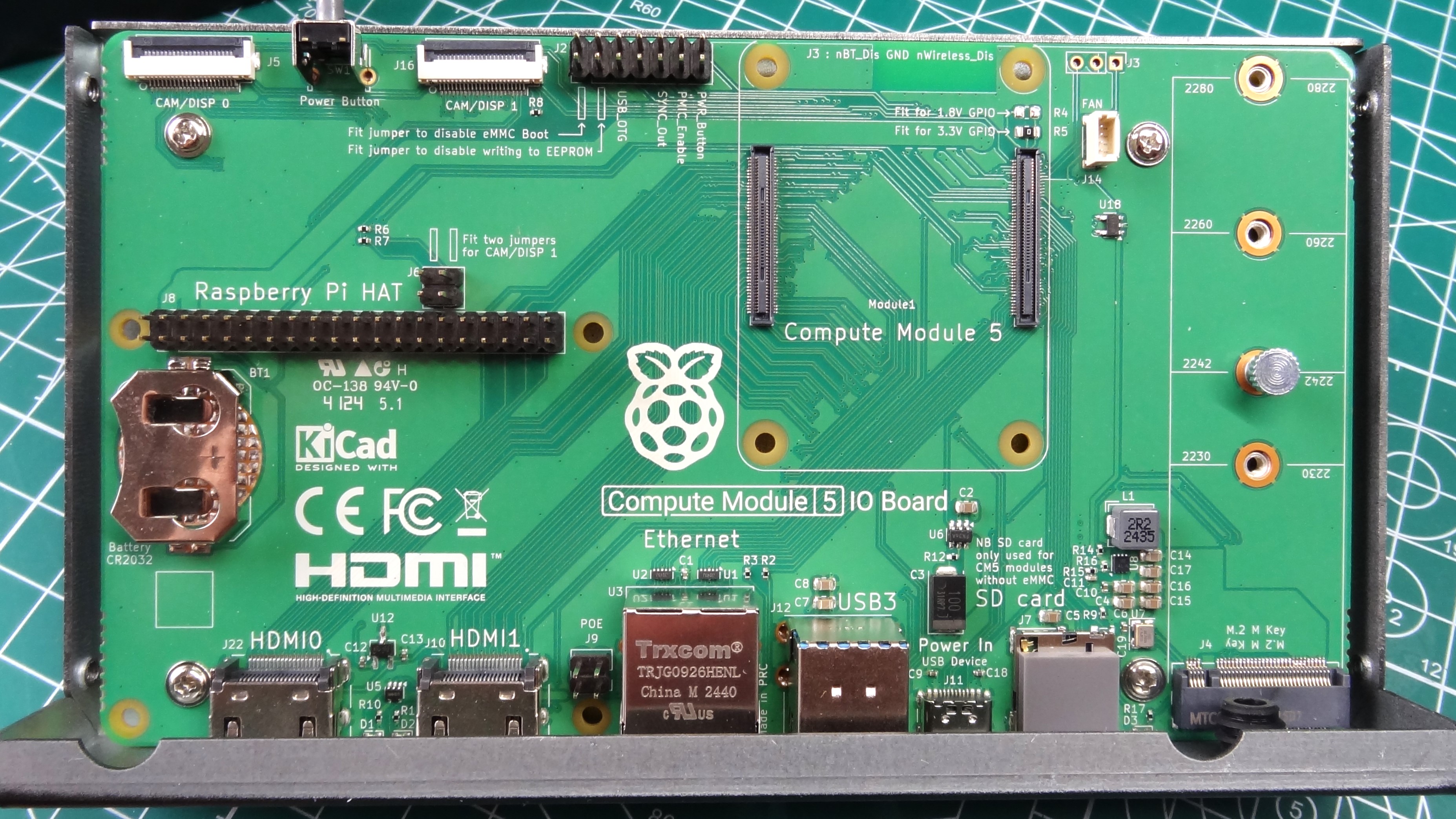
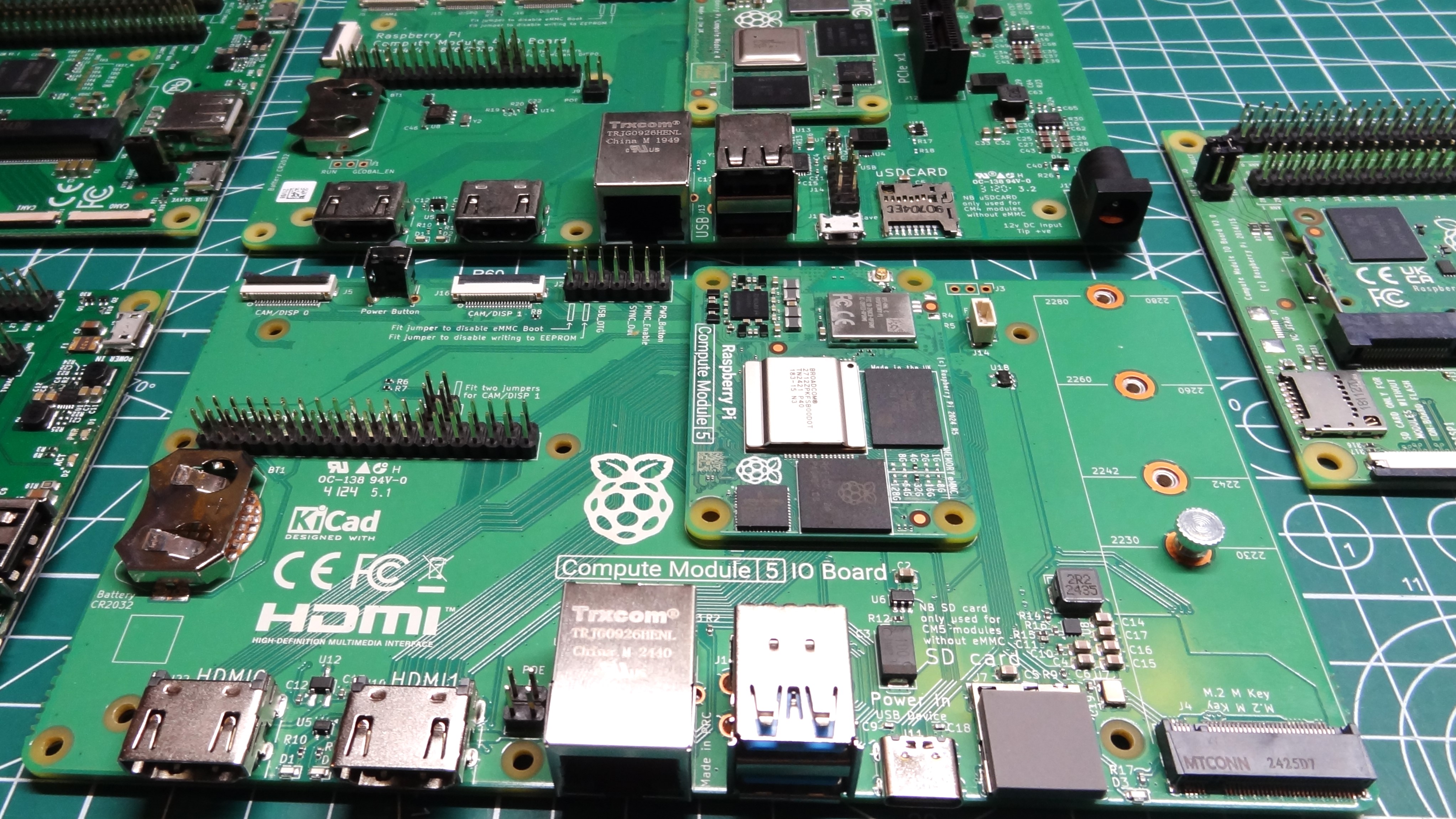
Every Compute Module has a development board, commonly referred to as the IO board. I’ve got a stack of them, from the very beginning, and now I have one more in the shape of the $20 Raspberry Pi Compute Module 5 IO Board. The IO board is where you design and test your Compute Module-powered product before you create a custom PCB on which to base your project.
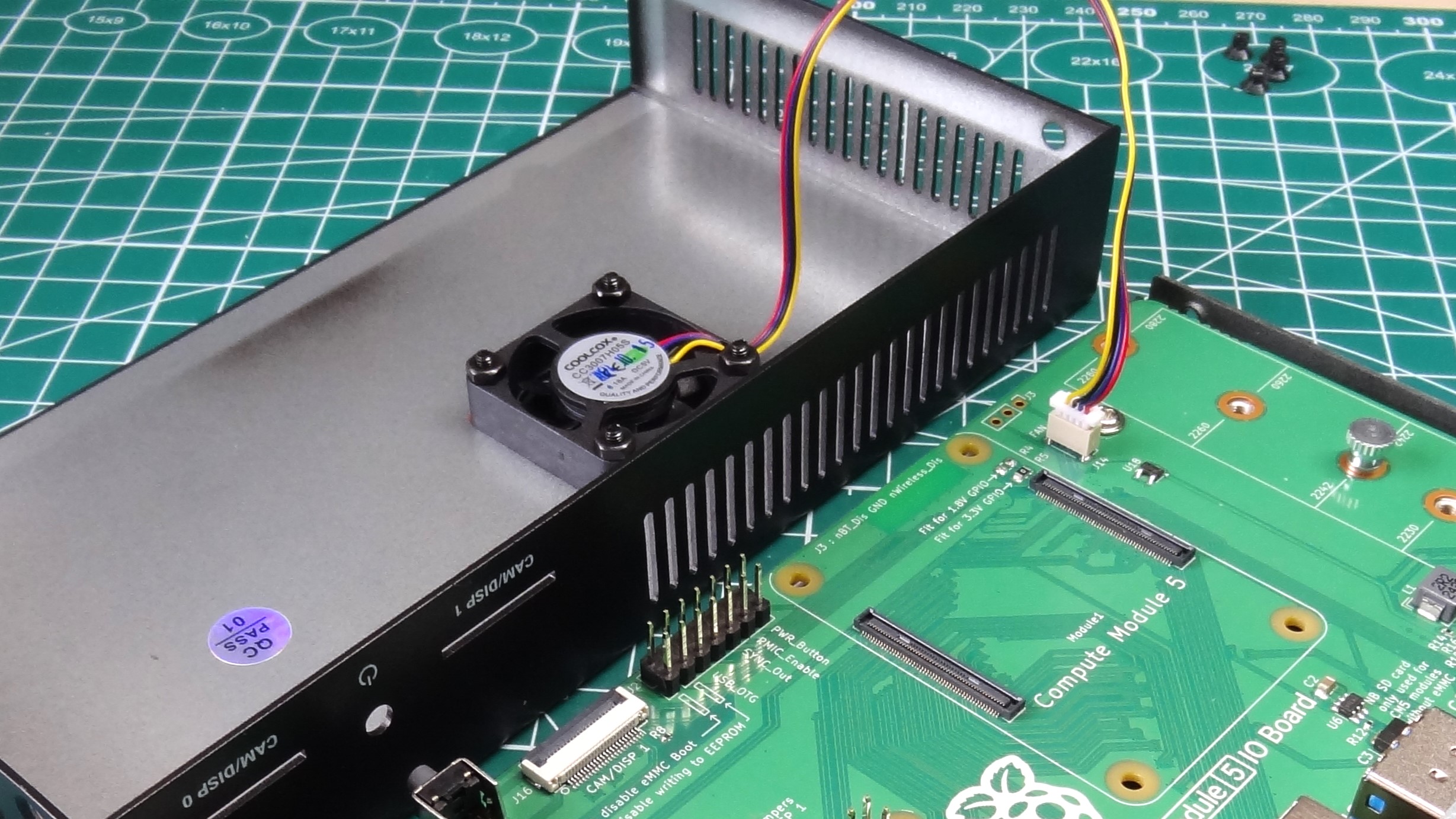
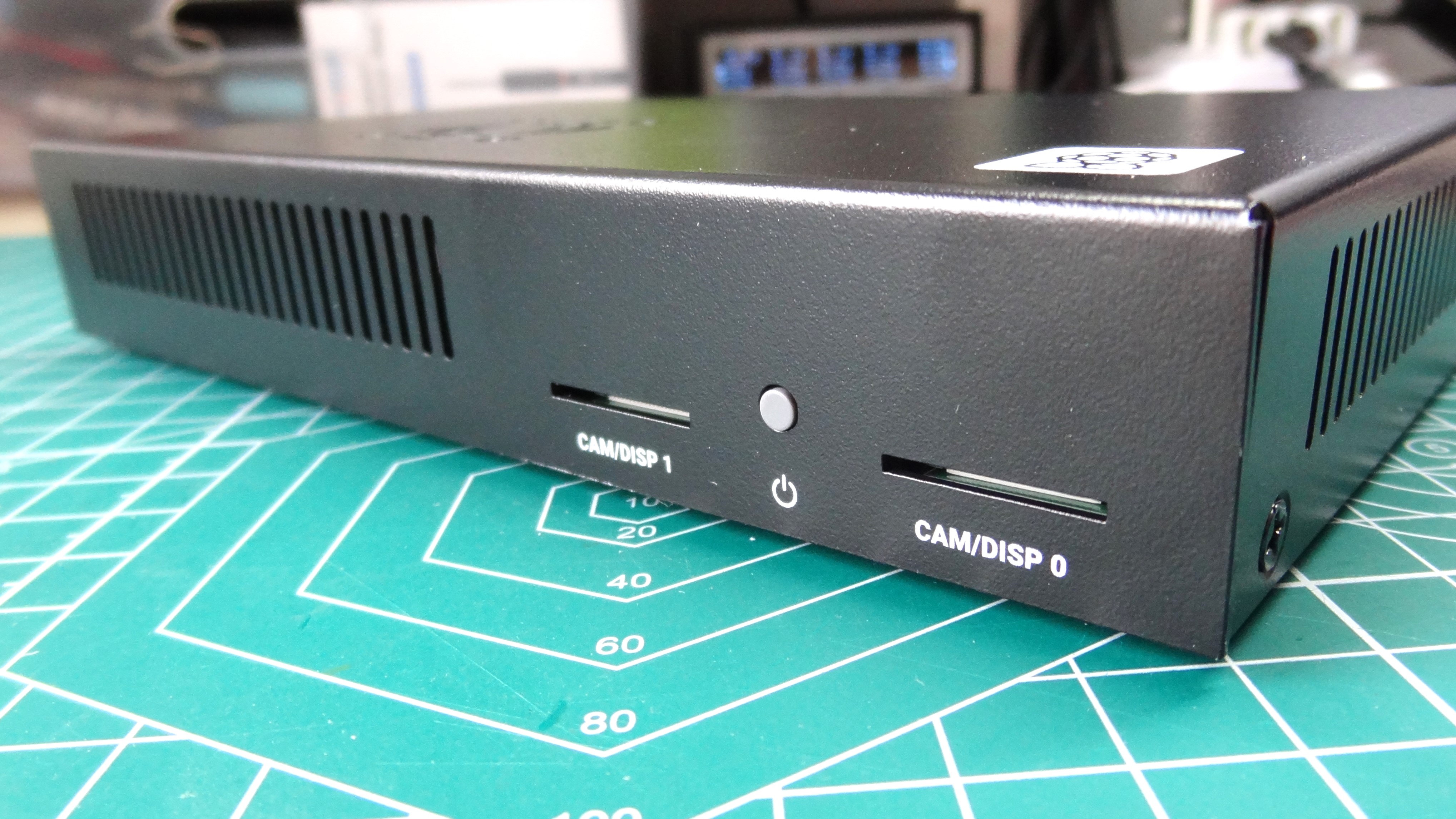
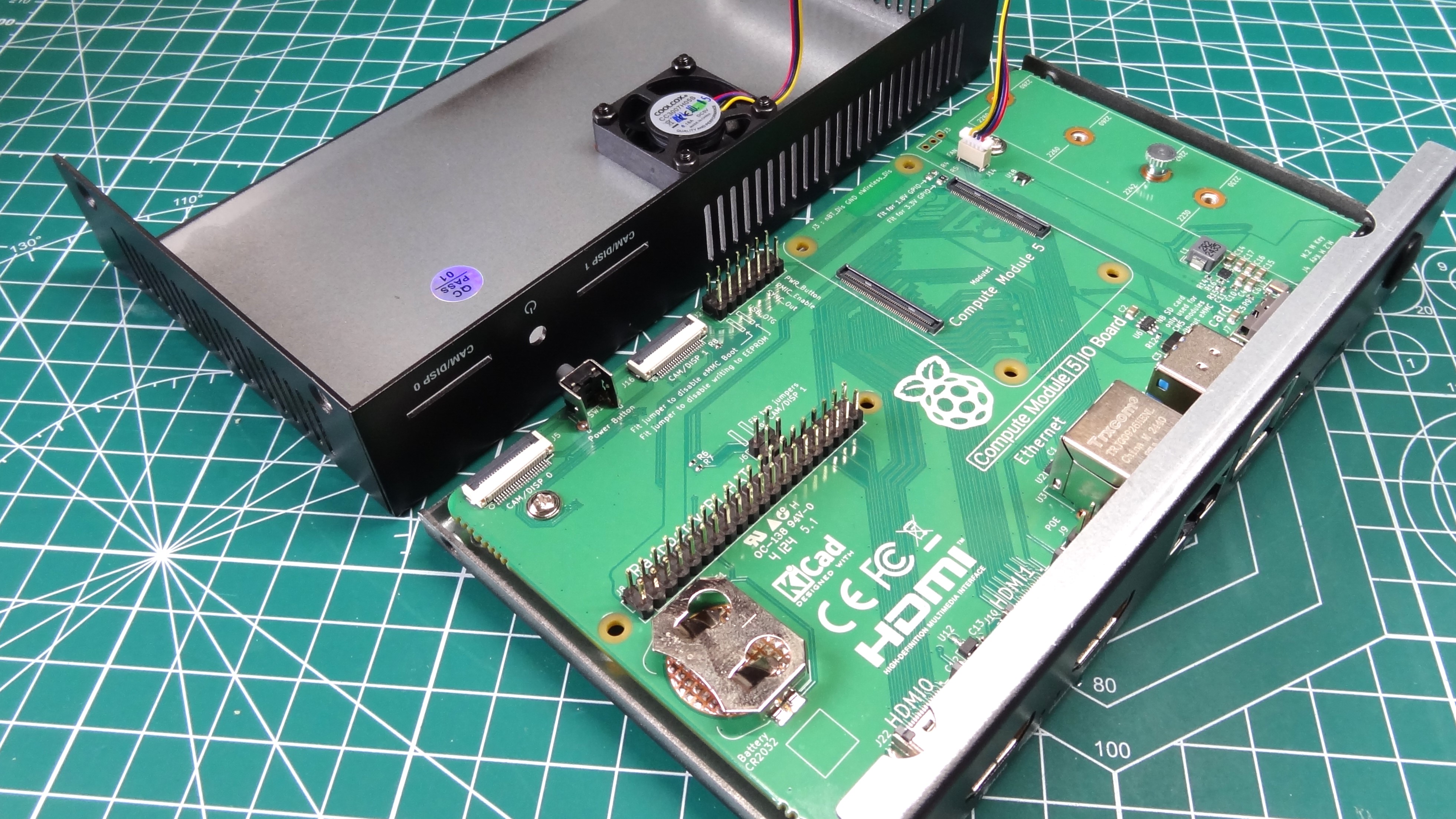
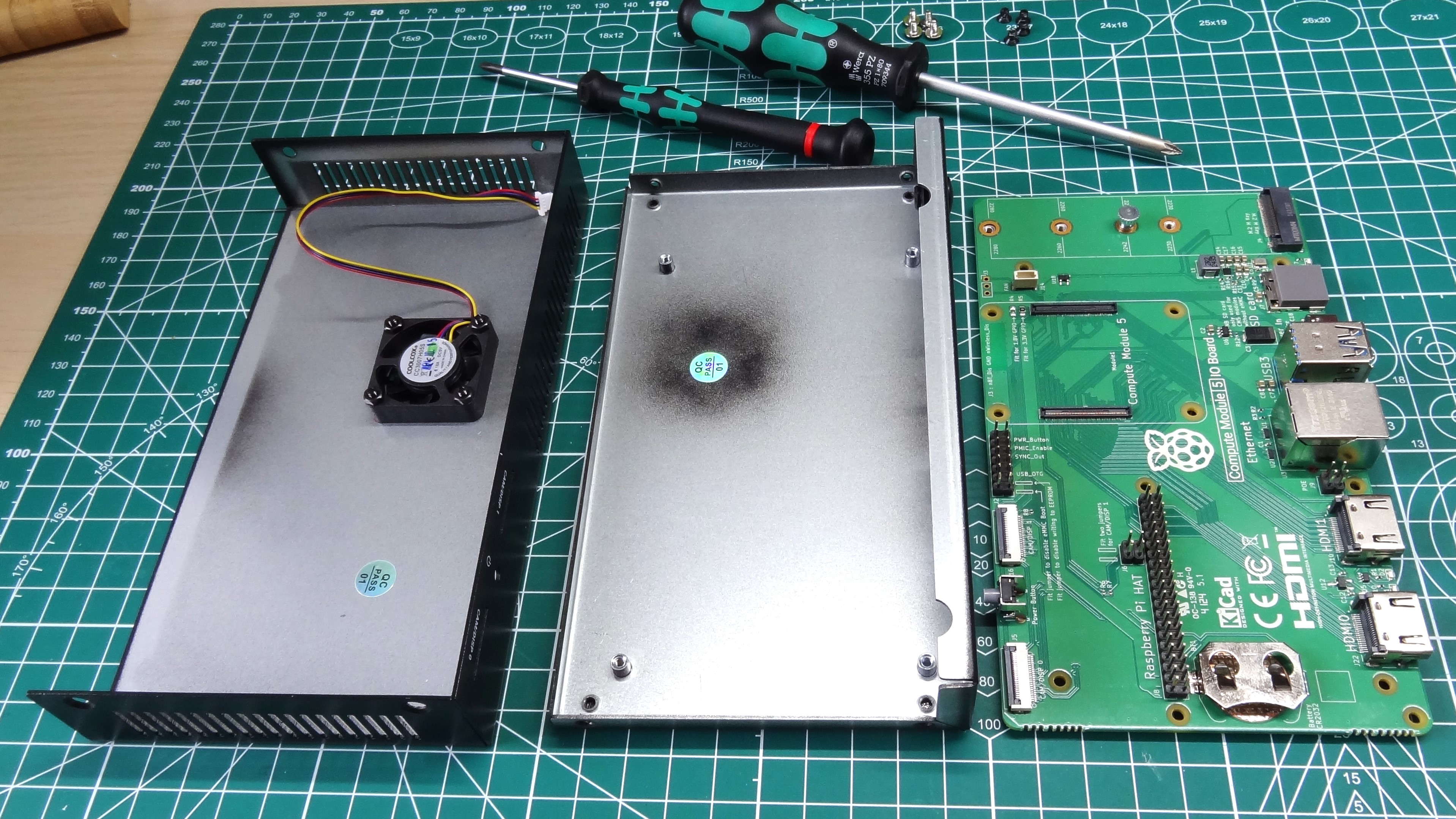
The IO board’s job is to give you everything that you need to build the project. On the board we have dual camera / display interfaces (which have a cutout on the case to route to the outside world), a full 40-pin GPIO, headers to manually enable / disable features (cameras, eMMC, USB OTG and EEPROM), a space for the Compute Module 5 to sit. Interestingly, the Compute Module 5’s IO board has an M.2 NVMe interface for use with SSDs and other PCIe based addons, like the Hailo-8L AI accelerator used in the Raspberry Pi AI Kit. There is also a connector for a cooling fan, it is pin compatible with the official active cooler, but there is nowhere to mount the cooler. Instead, the fan is connected to the top of the case.
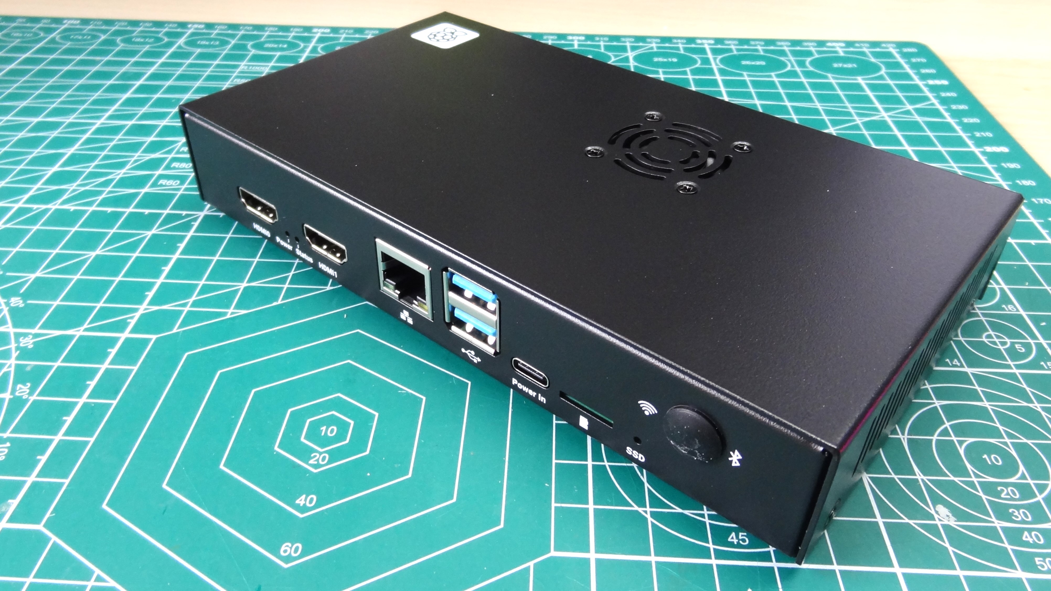
On the front of the IO board are two full size HDMI ports, Gigabit Ethernet, two USB 3.0 ports, USB Type-C power and a micro SD card slot (for non-eMMC CM5). Around the back are the aforementioned dual camera / displays connectors and a power button. You can also wire your own power button to the J2 header, useful for breaking out the connection.
This IO board is a little different from the previous, because it fits into an optional $15 metal case. It may look like an industrial control box, but this is the first time that the Compute Module has come with its own case, and it looks pretty good. Ok, I’m not going to give this pride of place in my living room, but for the office / workshop / industrial sector, it looks “the business”. And, we can mount the included Wi-Fi / Bluetooth antenna to the chassis, and use the active fan (which hangs too far away from the SoC).
Using the GPIO on the Raspberry Pi Compute Module 5 IO Board
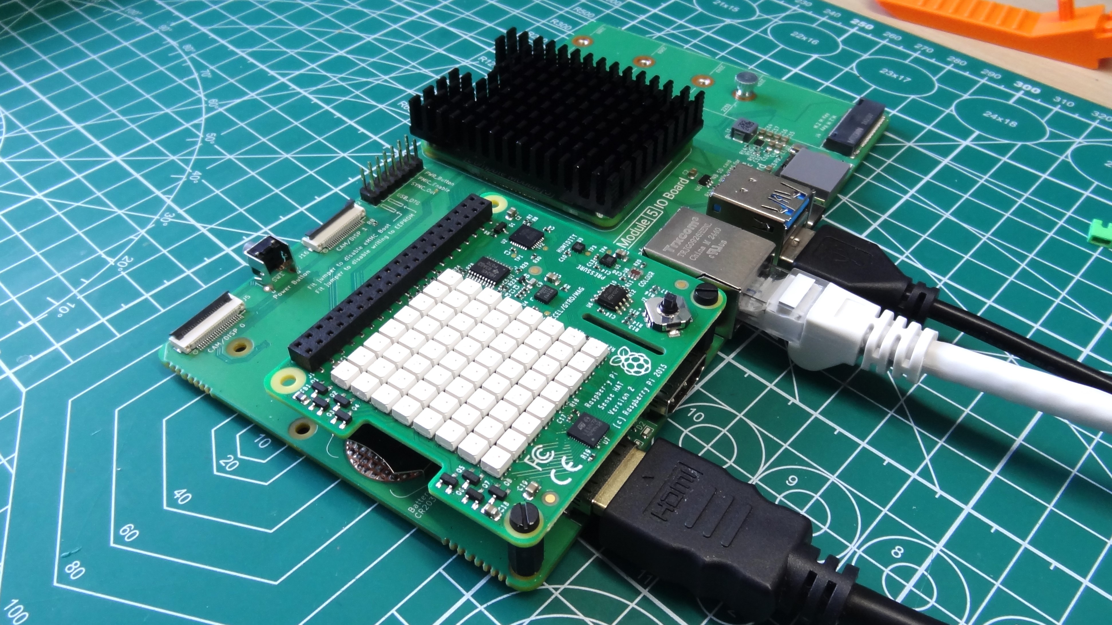
The Raspberry Pi’s GPIO (General Purpose Input Output) pins are where we can interact with electronic components and build projects that work with the real world. I’ve made so many projects over the last decade that involve the GPIO pins of a Raspberry Pi, and Python. With the release of the Raspberry Pi 5, and its RP1 chip, the way that we interacted with the GPIO changed, for the worse in the short term, and hopefully for the better in the long. Instead of “bit banging” the GPIO in memory, we now have a proper interface with which to use the GPIO, but this caused an issue for libraries, such as RPi.GPIO which relied on the older method of interaction.
How important was RPi.GPIO? Very! It underpinned a considerable amount of Python modules, relied on by the best Raspberry Pi HATs and this caused lots of work for Python software maintainers, who also had another hurdle in their way.
Python guideline PEP668 now requires us to use virtual environments to manage our Python code so that we don’t interfere with the underlying operating systems Python installation. This is a good practice, and something that I have now personally adopted. But the mix of RP1 and PEP668 caused a headache for Python software maintainers who are still facing issues with running their code on the Raspberry Pi 5.
That was a lot of exposition just to say, your mileage may vary. For basic GPIO tasks, you’re good. Blinking LEDs, buzzers, buttons and motor control is all good. As is reading simple sensors. If your add-on board uses I2C, SPI or other more exotic protocols, check before you purchase. I tested Raspberry Pi’s Sense HAT, a board with temperature, humidity sensors along with an accelerometer, magnetometer and color sensor which connect using I2C. This worked perfectly, as expected for a first party board. Other boards from third-party vendors will require a little home work before you make a purchase.
Using the Raspberry Pi Cameras and Touch Display 2 with the Raspberry Pi Compute Module 5
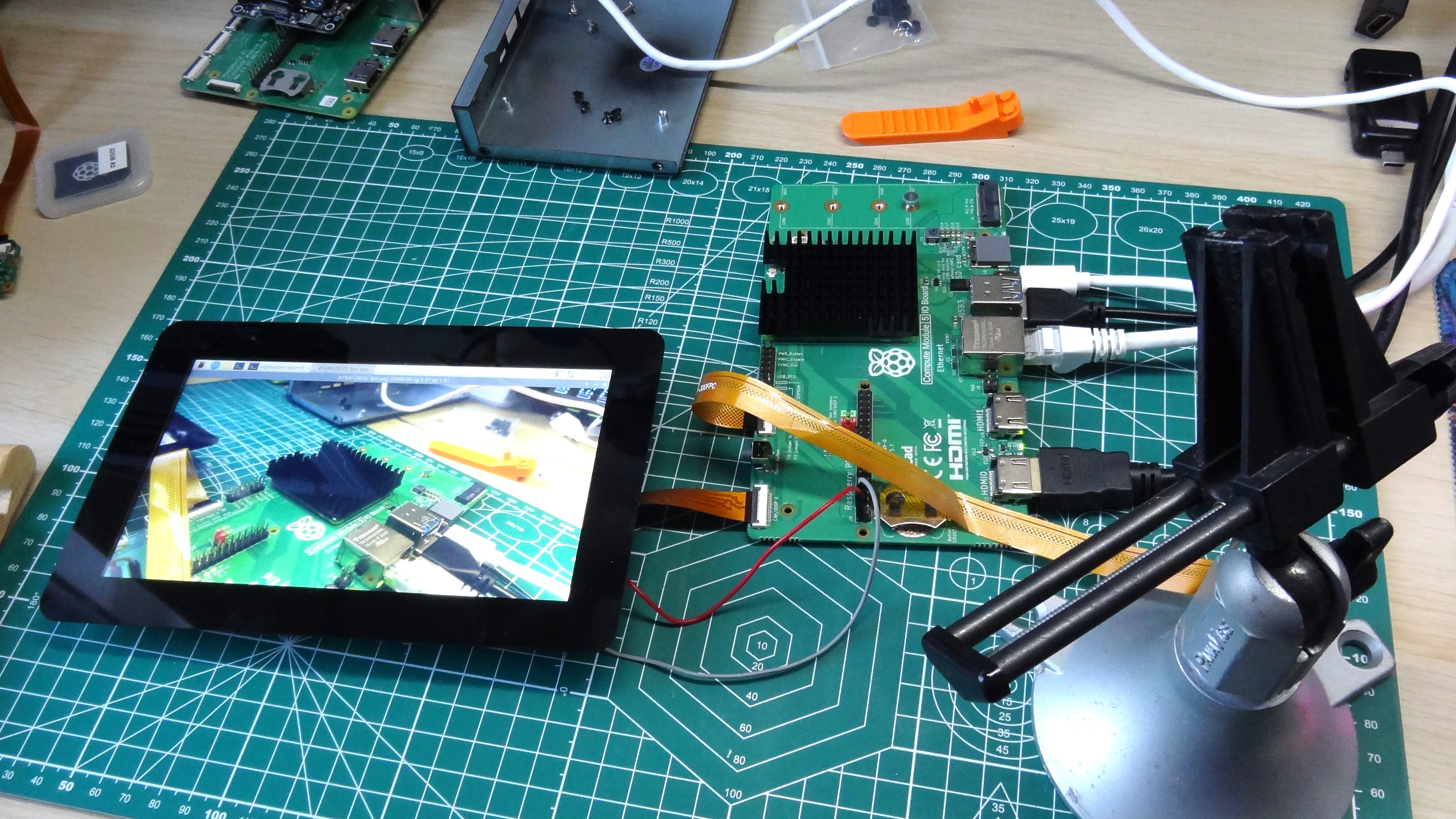
The dual MIPI connectors on the CM5 IO board are dual purpose. They can be used with two cameras, two Touch Displays or a mix of both. They both use the same connectors and FFC as the Raspberry Pi 5, so no need to purchase any adapters. They connect up, lock in place and are ready for use, once we have tinkered with the config.txt file. It took a little time with the Raspberry Pi engineers to spot a user error (my bad) and to work out the correct configuration details, but once it was tweaked, everything ran smoothly. End users should not have this issue, I took one for the team, as a commit has already been made to GitHub to resolve this issue.
Who is the Raspberry Pi Compute Module 5 for?
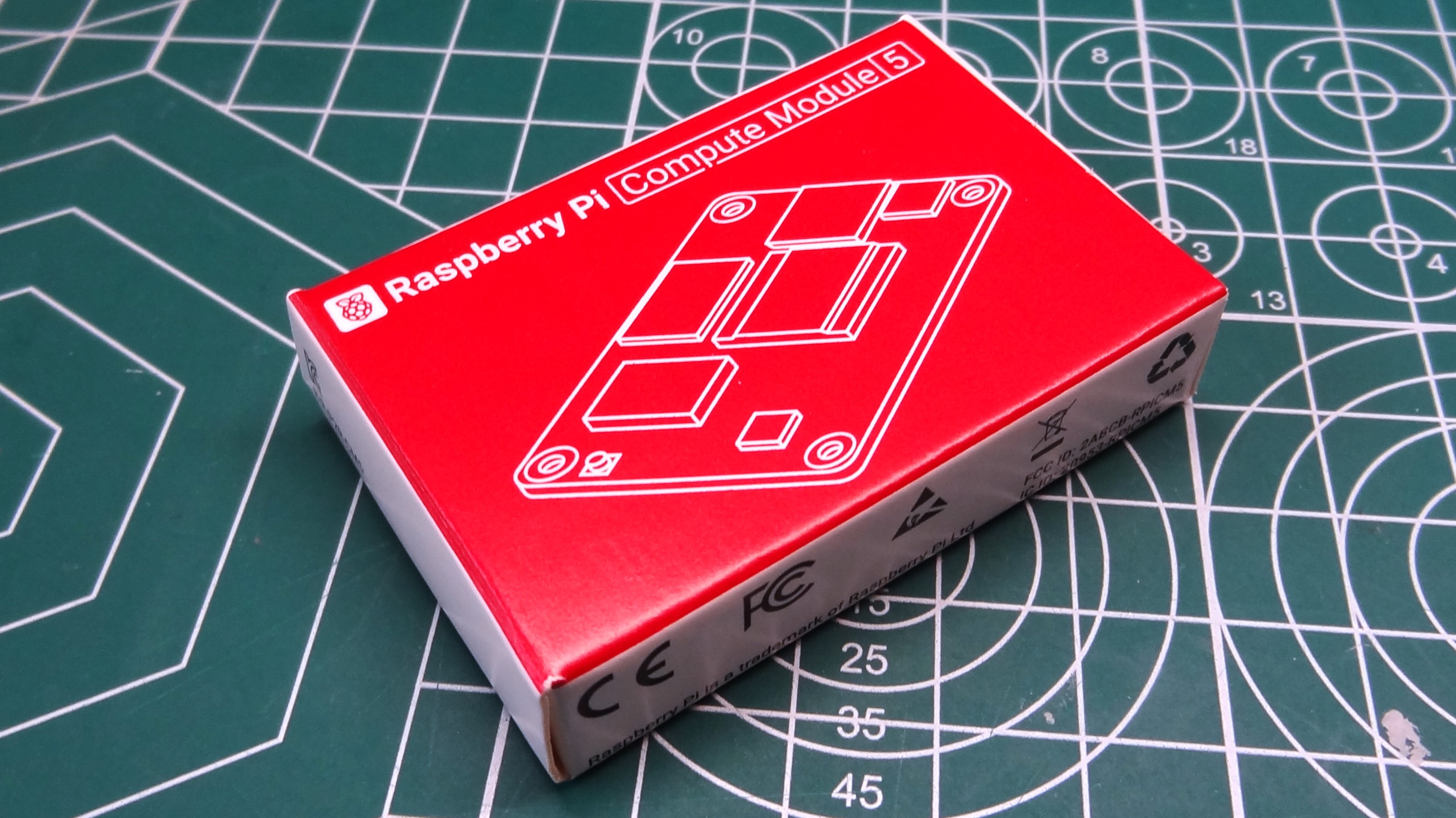
As with all the previous Compute Modules, they are ultimately destined for makers / creators who want the power of a Raspberry Pi in a much smaller form factor. Typically they are used in industrial and consumer electronics, but the maker community embraced the platform to use in its projects.
With the CM4 we’ve seen AI-powered bird cameras, NAS, even handheld retrogaming consoles. All of these can potentially be powered by the Compute Module 5. If someone was clever enough to make a PCB, then the CM5 could be used with the new Raspberry Pi Touch Display 2 to create a portable Pi tablet.
Bottom line
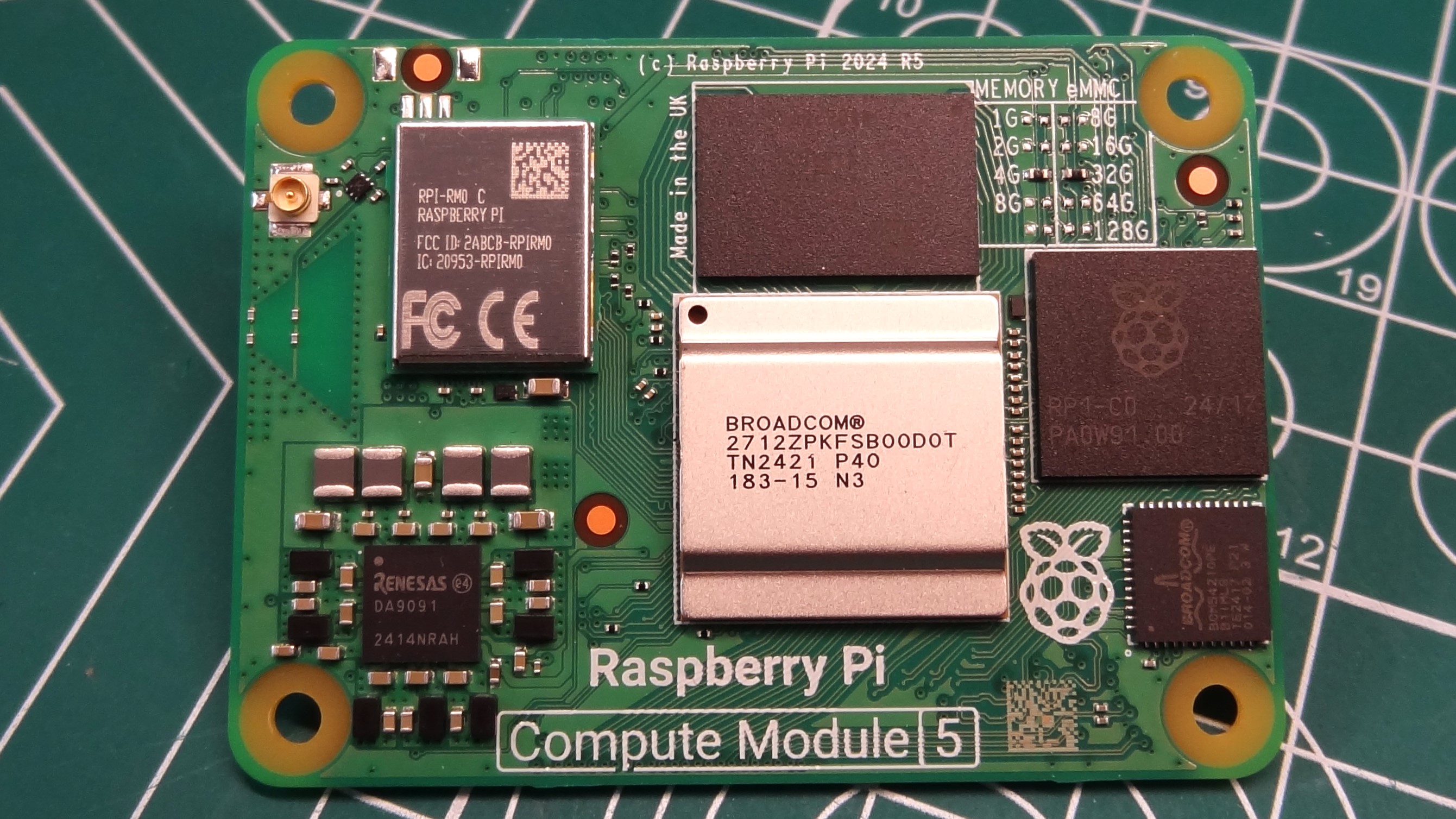
The Compute Module range of Raspberry Pi offers the power of the flagship Raspberry Pi 5, slimmed down into a package made for embedded projects. This isn’t a board for everyone, but if you need the power of the Pi 5 in a much smaller package, and you are prepared to design a custom PCB (or just wait for others to do so) then you have a potent platform from which to build projects and products.
